Juko XT ST-12
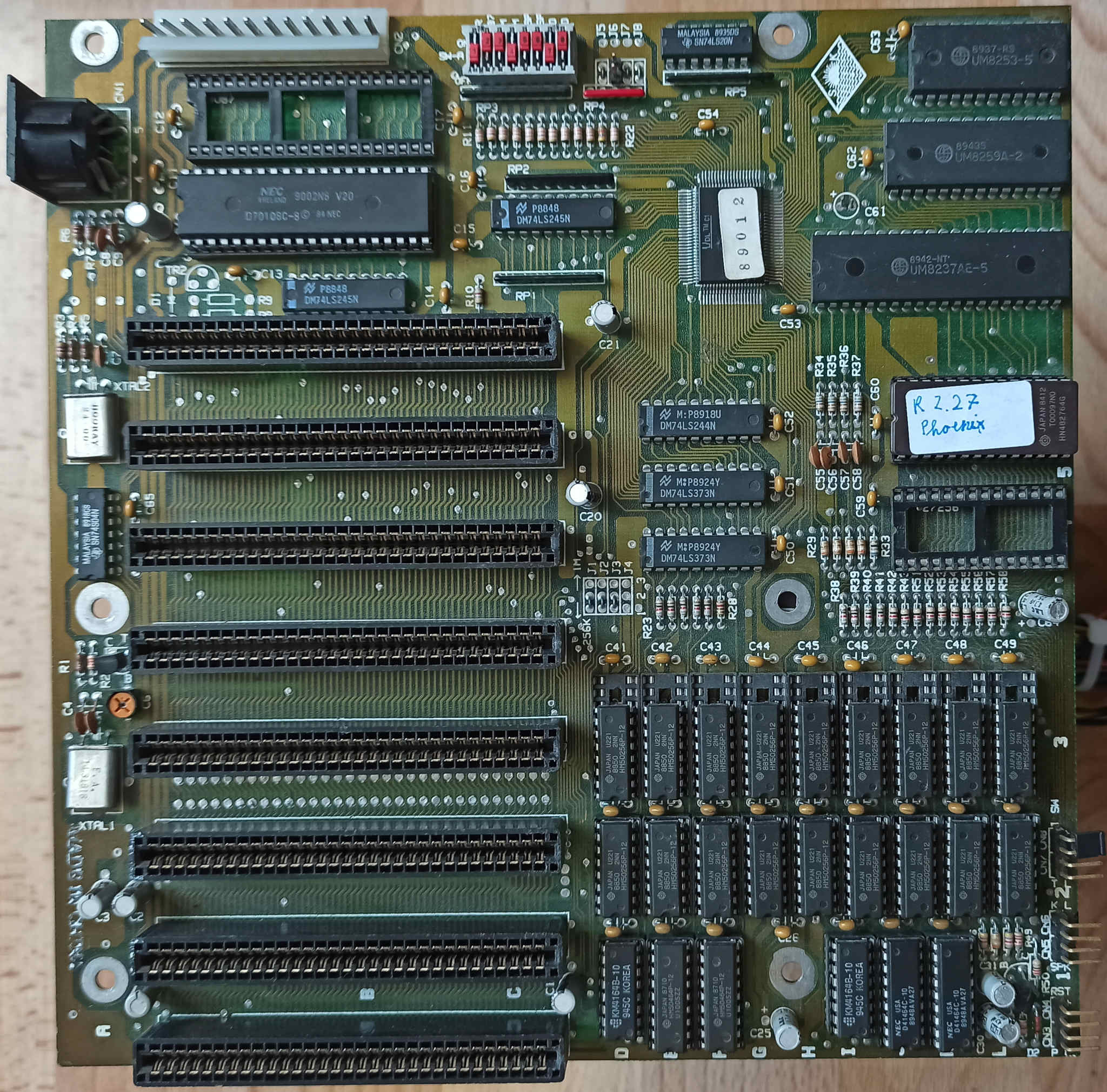
Chipset
The whole board has a 8-bit bus. There are two slots for ROM chips, they are likely mapped to successive locations.
- NEC V20 CPU (Intel 80188 compatible)
- Propietary Host bridge, which also implements the keyboard controller (surface IC on top right)
- 640kB of Hitachi HM50256-based DRAM
- UM8253-5 Programmable Timer
- UM8259A-2 Programmable Interrupt Controller
- UM8237A DMA controller
There is no RTC or NVRAM. The BIOS settings are entered via on-board jumpers.
Connectors
- AT Power Connector
- 5-pin AT Keyboard connector
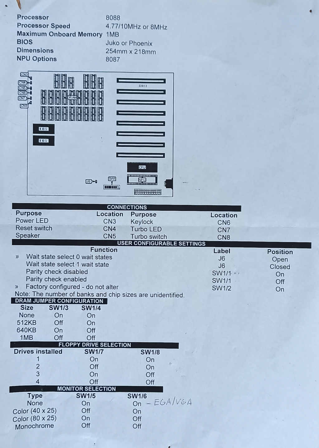
Control & status header
The headers for the switches and LEDs are on the bottom right of the picture. Starting from this corner and moving up:
- 2 pins: Power LED
- 2 pins: Reset switch
- [gap]
- 2 pins: Speaker (controlled via PIT)
- 2 pins: Keylock
- [gap]
- 2 pins: Turbo LED
- 2 pins: Turbo switch
Writing on the PCB adjacent to these connectors indicates their purpose.
BIOS settings
Between the processor and the host bridge is a 8-bit DIP switch. The switches are numbered:
- SW1: Parity check for comms
- SW2: check for 8087 coprocessor
- SW3-4: On-board RAM:
- 00: 1 MB
- 01: 512 KB
- 10: 640 KB
- 11: none
- SW5-6: Display mode:
- 00: MDA card
- 01: 40 x 25 color CGA
- 10: 80 x 25 color CGA
- 11: Defaults from graphics card
- SW7-8: 4 minus number of installed floppy drives
Nearby there is a single additional jumper enabling an extra wait state on the ISA bus. You should keep this enabled if the board is running with more than 4.77 MHz, like when turbo is enabled.