Amstrad Schneider PC 1512
- Intel 8086 CPU @ 8 MHz
- 512 kB RAM
- 5 1/4-inch floppy as A:
- XT-IDE ISA card with slot for Compact Flash disk as C:
- Runs MS-DOS 3.2 (OEM Version)
- Fanless (but the CRT makes different kinds of noise)
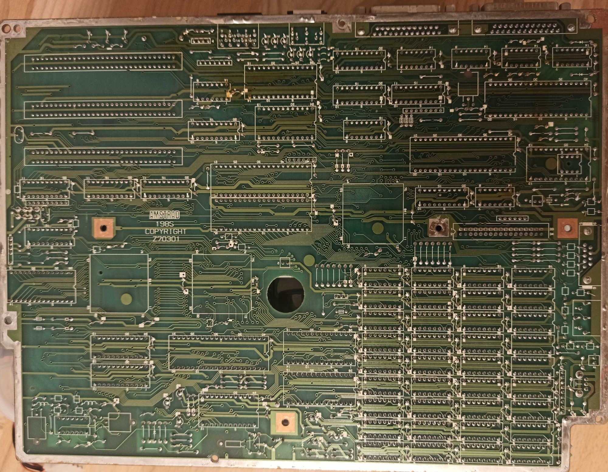
Mainboard and Processor
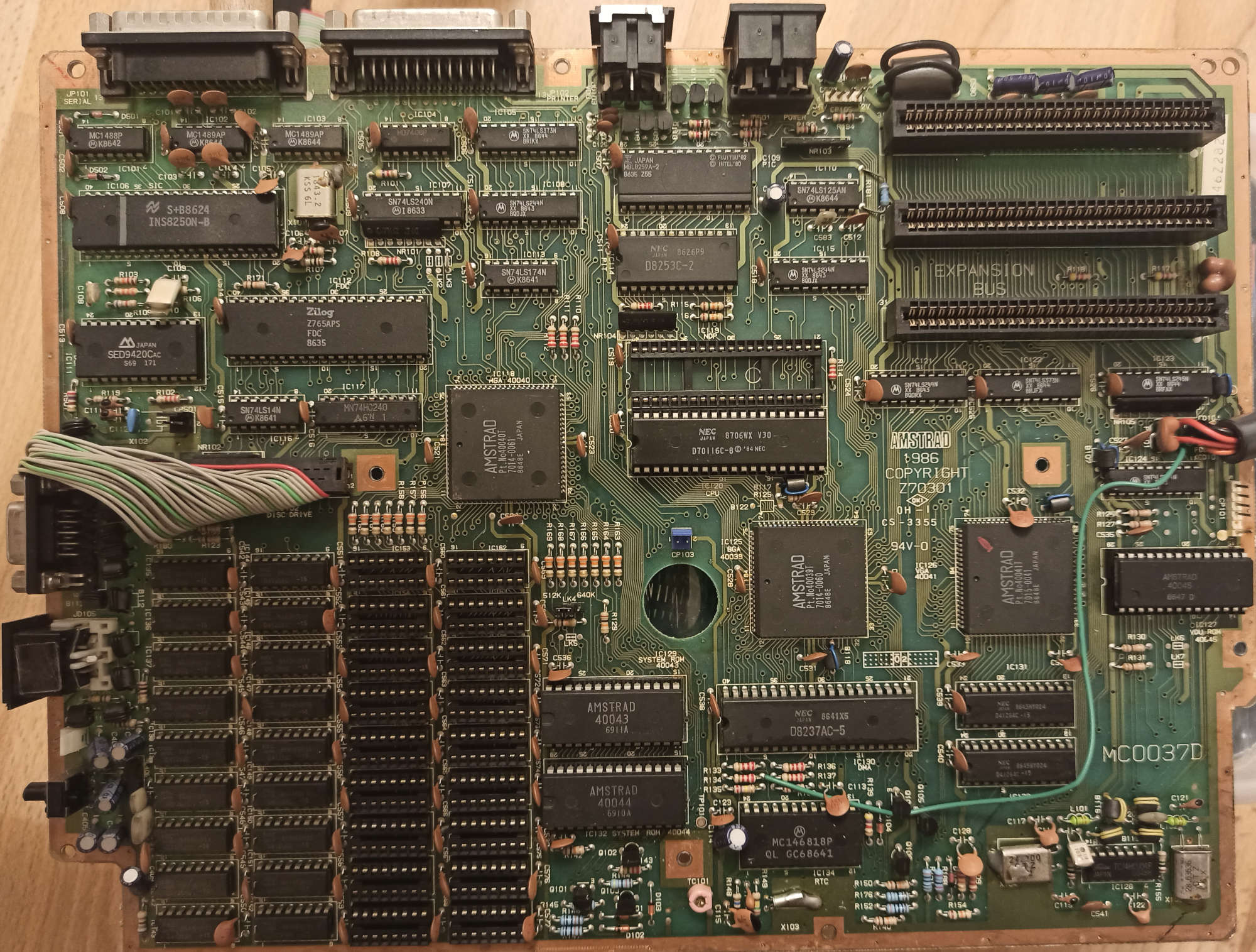
Originally the Mainboard had a Fujitsu MBL8086-2 CPU, which is a CMOS variant of Intels 8086. I ordered a NEC V30 CPU off eBay as replacement - this was meant to make debugging easier since the V30 has an invalid opcode handler. Using that, its at least possible to catch runaway instruction pointers. In addition to that, the NEC V30 offers the following features:
- Faster execution speed (has dedicated addition unit for indirect addressing)
- 8080 emulation mode
- 80186 instruction set (noteworthy: PUSHA and POPA)
- More bitwise operations
Harddisk via XT-IDE
I wanted to have a persistent storage that i can move between the Amstrad and my other computers. For IBM PC compatibles in 2019 it seems common to use a ISA card with a on-board Compact Flash (CF) card.
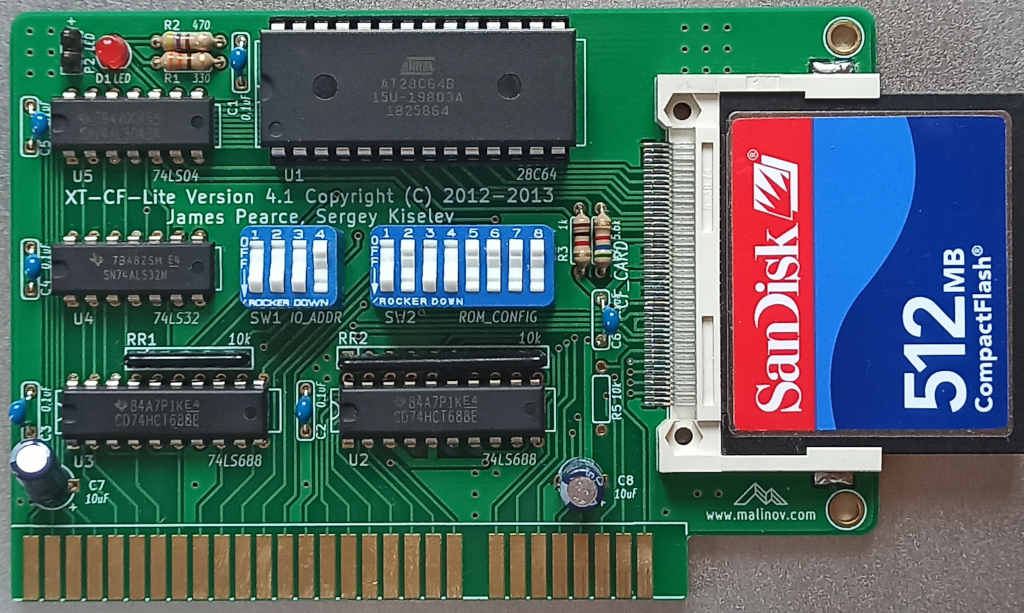
The XT-IDE card features an EEPROM with contains a option ROM for the BIOS. The Card will make the ROM available inside of the adressable range of the system memory between 0xC8000 and 0xE0000, which is designated as "Reserved Area" by IBM. Due to the nature of the ISA Bus, all the card has to do for that to work is to put data on the bus when it sees its own address on the address lines. Because several ISA cards could do that at once, the user needs to take care that there are no address range overlaps between cards and internal components.
During startup, the onboard BIOS searches parts of the reserved address ranges for ROMs located on external cards. If found, they are called and might register their own interrupt functions. The XT-IDE card hooks into interrupt 13h to provide disk access. The BIOS later uses the interrupt 13h services to boot from the CF card.
Documentation on this XT-IDE card can be found on malinov.com.
Compact Flash card on MS-DOS
The fdisk shipped with the Amstrad version of MS-DOS is not able to create a master boot record on its own. In addition, it also fails for disks larger than 32 mebibytes, which is 2^16 sectors with a sector size of 512 bytes. fdisk from util-linux allowed me to partition the disk from Linux. Following options need to be taken care of:
- Partition must be primary and in the first 32 MB of disk (last sector 65535)
- The active/bootable flag must be set ('a' command)
- The partition type must be set to 1, which is not the default
You know you did everything correctly when MS-DOS does recognize the existence of a drive C:, even when you cannot properly access it yet. Format the disk with the following command:
A>FORMAT C:/S
This also installs the kernel and command interpreter on the new disk and makes it bootable. You still cannot actually boot the disk since it doesn't have functional bootcode in the MBR yet. I fixed that by writing that code myself.
You can download the assembly from here. Dont forget to fill in your static partition offset! Compile it with nasm and write it to your disk:
nasm -o mbr.bs mbr.asm
dd if=mbr.bs bs=16 count=8 of=/dev/sdb
The mbr code is incredibly hacky but it works. Please dont judge me for it.
Serial access
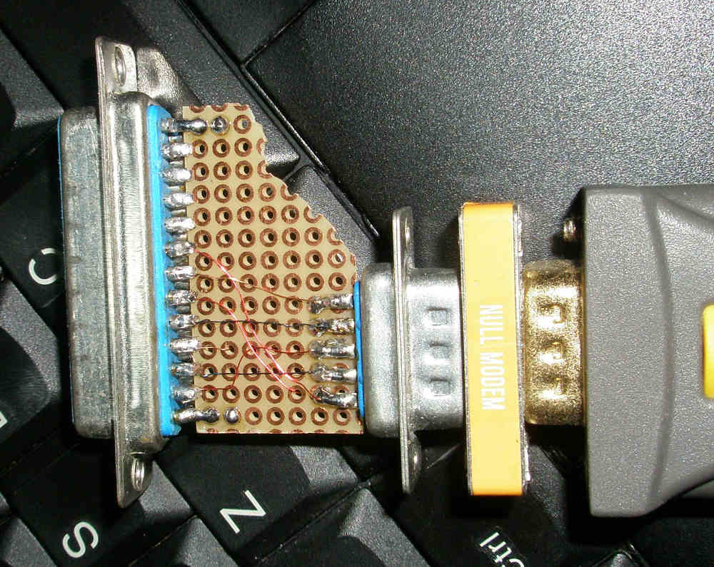
I soldered both an male DE9 and a female DB25 port together. The DE9 port was choosen to be male to fit the standard form for PC-side ports.
I used this as reference for the wiring. For archival purposes, i reprint the table here:
| DE9 | DB25 | Function |
|---|---|---|
| 1 | 8 | Data carrier detect |
| 2 | 3 | Receive data |
| 3 | 2 | Transmit data |
| 4 | 20 | Data terminal ready |
| 5 | 7 | Ground |
| 6 | 6 | Data set ready |
| 7 | 4 | Request to send |
| 8 | 5 | Clear to send |
| 9 | 22 | Ring indicator |
The pin numbering is usually imprinted directly next to the pins, difficult to read. Because i had choosen a male DE9, connecting it to another computer requires a nullmodem adaptor or cable.
For the actual transfer, i choose 9600 baud, 8 bit, no parity and 2 stopbits. On the linux side, one can connect to the tty as follows:
screen /dev/ttyUSB0 9600
Depending on your serial adapter, the device might be called differently.
On MS-DOS side, you have to setup the communication port as follows (i got this line from the original documation that i still had with the device):
C>MODE COM1:9600,N,8,2
With the communication port configured you can instruct MS-DOS to read commands the COM1 port:
C>CTTY COM1
Remote reset
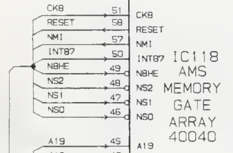
The mainboard does not have means to reset it - in case of crashes, the user was expected to do a power cycle. To help automation and enable remote control, some facility to trigger resets externally is needed. In the Service Manual i discovered some sort of schematics showing that all reset pins of the various chips on the board are all wired together. At first i couldn't find a source where the reset actually came from. The list of I/O ports in the technical manual lists port 66 as causing a reset when being written to. Combined with the little arrow in the schematic to the right, im assuming that the reset signal is only generated by the address decoder for the system memory (AMS 40040).
I decided to bypass the decoder alltogether and successfully forced a reset by connecting the reset rail with the +5V rail using the free connectors in the FPU slot.
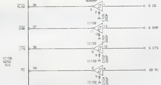
To be able to do a reset remotely as part of interfacing the Amstrad via serial, i considered implementing a similar kind of auto-reset like the Arduino does. When opening a serial console to the arduino, the DTR line gets asserted, which is connected to the controllers reset pin via a capacitor. The 8250-compatible UART controller has support for those control lines as well. I gave power to the mainboard, connected the RS232 and measured the voltages on pins 36 to 39 of the UART relative to the mainboards ground. After launching a screen session on that port, i measured again. Take into account that this table reflects the levels between the UART receiver (1489AP) and the UART controller.
| Pin | Idle | Active |
|---|---|---|
| 36 / CD | +5V | 0 |
| 37 / DSR | +5V | 0 |
| 38 / CTS | +5V | 0 |
| 39 / RI | +5V | +5V |
The Ring Indicator (RI) pin did not change, which is quite reasonable, since RI is usually send by a modem to signal an incoming call. Since i have two machines talking to each other via a nullmodem cable, there is no modem involved. The Clear-to-Send (CTS) pin is used for hardware flow control and might be asserted by the peer during transmission of data. The Carrier Detect (CD) and Data Set Ready (DSR) pins are both driven by the remote Data Terminal Ready pin when using a nullmodem cable. They seem to be a good choice to connect the reset pin to.
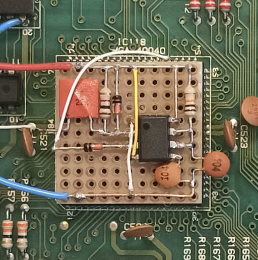
While doing pre-fabrication research, i found that the reset line draws 50 mA when asserted. The UART receiver chip is only able to supply 20 mA at most, so i asked a friend to help me with the circuit design. We managed to solve it with an NE 555 in monoflop configuration. This yielded several advantages:
- A NE 555 can give a short pulse, thus there are no 5 V * 50 mA = 250 mW being burned while there is no serial connection
- Said chip can also directly deliver up to 200 mA, so no further transistors are necessary
- The circuit is simple enough that it could be built from scavenged parts that i had available
I had to make one change when the circuit was installed in the system. The POST setup was failing with "Error in the Interrupt Controller", and i figured it was because the circuit pulled down the reset line during boot, which prevented a proper reset on power on. I fixed this with a diode that only allows the NE 555 to pull up the line, but never down.