Trend DT 486 SX-25
- Intel 80486 CPU @ 25 MHz
- 4 MB RAM
- 6 16-bit ISA slots
- 3 1/2-inch floppy as drive A
- 5 1/4-inch floppy as drive B
- Most devices not on-board, but via multi-IO card
Mainboard and Processor
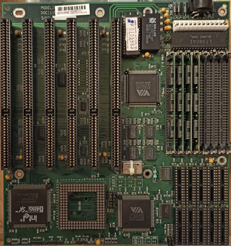
The processor is an Intel i486SX running on 25 MHz. Originally, these CPUs were i486DX rejects with a defective FPU. The CPU is soldered to the corner of the Mainboard and is not replaceable itself. The Mainboard itself has a 5-pin DIN port for the keyboard. All storage and display options are done via 16-bit ISA cards.
With the PC came a graphics card with VGA output. Said card brings its own int 10h services via ROM. A multi-IO card provides a MFM port for floppy drives, an ATA port for hard drives, two serial ports, a parallel port and a game controller port. This leaves 4 slots for other cards.
Originally i assumed that the reset button was broken, but upon disassembly i discovered that the two reset buttons are wired serially and thus need to be both pressed at the same time to reset the board.
BIOS and CMOS battery replacement
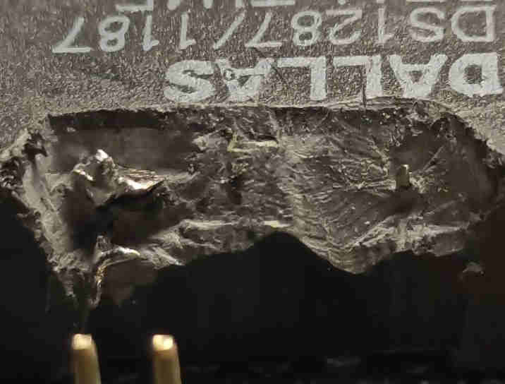
The BIOS requires that the CHS geometries of the internal disk and the floppy drives are correctly set up. There is no support for linear block addressing, thus the CHS setup is a requirement for booting from a disk at all. The geometry information is saved in the non-volatile ram in the realtime clock (called RTC from now). The RTC is a Dallas 1287 that is soldered directly onto the mainboard, the battery to retain the nvram state is casted into the RTC casing and thus not accessible. Of course it was empty after almost 3 decades.
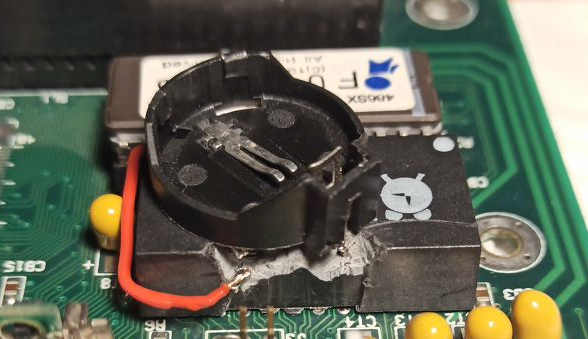
After some research i learned that the DS1287 can be cut open to access the battery lines and supply them externally. The DS1287 is actually just a regular DIP chip with certain pins bend up instead of down towards the PCB. The space above the chip contains the battery and the oscillation quartz, but the whole thing is casted into some material that is now solid. I spent two hours cutting into the plastic encasing and the cast and found two pins. To verify that i had indeed found the battery wiring, i measured the voltage between those two pins and got 300mV with the expected polarity. The battery ground (left side in picture) exposed a solder joint which i could disconnect. Getting an cr2032 battery holder on top of it was trivial.
Internal Hard Disk
With the CMOS data now persistent, i took the hard disk and transferred the geometry inscribed onto the decal into the BIOS settings. As a result, the machine became able to boot from the internal hard disk. The HDD had a full MS-DOS 6.22 install with file modification times from May 1994.